


In this article we will give you information on how to control simple DC motors. First of all, we’re going to talk about DC motor control with the transistor. We will then examine the DC motor control circuit modules.
First of all, let me show you what I mean by cheap and simple DC motor mechanism:

You can find the DC motos above everywhere. Usually the wheel comes with the DC motor.
In these motors, two parameters are important:
1- Operating voltage (Usually 6 Volts or 12 Volts.)
2- Number of speeds (These motors are reducer motors. Therefore, the number of cycles is below a certain value.)
First, let’s look at how we can control these motors in a simple way.
DC Motor Control Circuits Principles
1- DC Motor Control with One Transistor or Mosfet
Various circuits are used to control DC motors. A DC motor can be controlled in its simplest form by triggering a single transistor:

In this circuit, you make the motor turn according to the voltage you will apply from the Data section. 0 V means motor stop, while 5 V means rotation at a certain speed. You can control the motor with a single transistor, but you can’t change the direction of rotation. You must use electronic circuits called H Bridge bridges to change the direction of rotation. If you think that the motor current is higher than the current that the transistor can pass through, you can use a transistor or mosfet with a higher collector current. For example, in the following diagram, the motor is driven with N channel mosfet.

2- DC Motor Control with Two Transistor Half Bridge Circuit

When a signal is applied to input 1 in the above circuit, the motor rotates in one direction and the motor in the other direction when the signal is applied to the other input. The transistors used can be type N or type P. You can also make higher current resistant circuits using mosfet.
The polarity of your signal to the IN inputs depends on the transistor you will use. If you use NPN, you must apply a positive signal to the IN input. If you are using PNP, you should also apply a negative signal.
3- Dc Motor Control with H Bridge Circuit
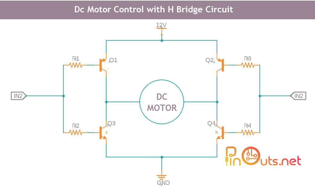
H bridge motor control circuit
There are 3 possibilities on the H Bridge bridge:
1- When a signal is applied to the IN1 input, the motor rotates forward.
2- When a signal is applied to the IN2 input, the motor rotates backward.
3- When signal is applied to both inputs, the motor stops. However, this is undesirable.
DC Motor Control Modules
A large number of DC motor control circuits are sold on the market. Moreover, most of them are very cheap. If you do not want to prepare the DC motor control circuit using the above circuits, you can also use a ready-made module.
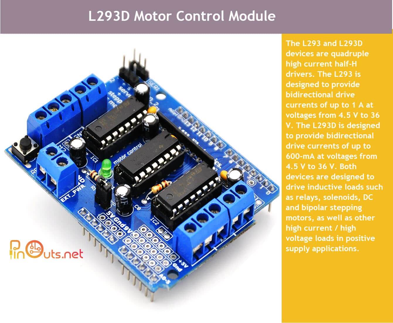
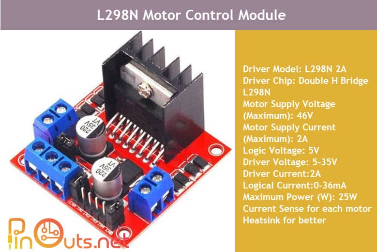
L293D and L298N circuits are the most affordable modules on the market.
DC motor control circuit, which will be used according to the current and power value of the motor you will use, will also vary:
- BTS7960B motor driver board: until 20 Amper
MC33926 motor control board: 3A – 28V
MC33926 dual dc motor driver board
TB6612FNG dual dc motor board (contunueously 1 A)
This topic is focused only on driving simple-build DC motors. Therefore, the details of the modules that control high-power motors are not discussed.
In this article we gave you information on how to control simple DC motors. We talked about DC motor control with the transistor. We contunued with DC motor control circuit modules. We will share simple and effective projects that you can do with DC motor mechanisms in next article. You can support us if you can share our posts on your social media accounts or leave comments.


 CNC Routers")
