


SparkFun MicroMod ST product line, the MicroMod STM32WB5MMG Processor brings together robust computing capabilities and wireless functionality within a single processor. Developed by STMicroelectronics™, the STM32WB5MMG is an ultra-low power microcontroller featuring a tandem of Arm® Cortex® processors: a Cortex-M4 processor for primary computing tasks and a Cortex-M0 processor dedicated to managing the 2.4 GHz radio. Notably, the radio is certified for Bluetooth® Low Energy 5.3, Zigbee® 3.0, and OpenThread.
Equipped with a range of interface and peripheral options such as SPI, multiple UARTs, I2C buses, and I2S, the STM32WB5MMG Processor offers versatility for various applications. This guide delves into the hardware components of this MicroMod Processor, provides instructions for assembling it into a MicroMod circuit, and outlines the steps for installing and utilizing the board with the Arduino IDE.
Hardware Overview
Let’s delve into the intricacies of the STM32WB5MMG and other components integrated into the MicroMod Processor.
STM32WB5MMG Multiprotocol Wireless Module The STM32WB5MMG module stands out as an ultra-low-power marvel, combining two Arm-Cortex processors to deliver a potent computing platform equipped with Bluetooth Low Energy 5.3 and 802.15.4 wireless capabilities. Featuring a Cortex-M4 CPU with FPU and ART for primary computing tasks and a Cortex-M0 for radio and security functionalities, this module offers a robust foundation. For a comprehensive understanding of the module, please refer to the STM32WB5MMG datasheet and application manual.
Highlighting the STMWB & Flash IC The STM32WB5MMG impressively offers a diverse range of interface options. The Processor strategically routes interfaces to the pinout on the M.2 connector, including:
- 2x UART (Standard and Low Power)
- 2x I2C
- SPI
- I2S[1]
- 16-bit Advanced Four-Channel Timer


The module showcases various low-power modes, notably a shutdown mode drawing a mere 13 nA and consuming 5.2 mA during radio transmission (Tx at 0 dBm). Utilizing an integrated chip antenna for the RF stack, the module achieves Tx output power up to +6 dBm, with an Rx sensitivity of -96 dBm for BLE and -100 dBm for 802.15.4 protocols.
W25Q128JVPIM Flash IC Augmenting its capabilities, the Processor incorporates a W25Q128JVPIM 128 Mbit (16 MB) Flash IC to provide additional storage functionality. The Flash IC seamlessly interfaces with the STM32WB5MMG through the QSPI interface.
Note: I2S control is not supported in the SparkFun Arduino boards package for this Processor. Users intending to utilize I2S with this Processor should opt for ST’s STM32Cube IDE.
Status LED A solitary LED on this board is intricately connected to the module’s PA2 I/O pin, serving as a status LED to provide visual feedback about the board’s operational state.
MicroMod STM32WB5MMG pinout
| STM32WB5MMG Pin | Primary Function | General Pin Description             |
|------------------|-------------------|--------------------------------------|
| -                | (Not Connected)  | 75	GND                              |
| -                | 3.3V              | 74-73	G5 / BUS5, PA0                |
| -                | V_BATT            | 72-71	G6 / BUS6, PH1                |
| -                | -                 | 70-69	G7 / BUS7, PH0                |
| -                | -                 | 68-67	(Not Connected)                |
| -                | -                 | 66-65	(Not Connected)                |
| -                | -                 | 64-63	(Not Connected)                |
| -                | -                 | 62-61	SPI_POCI (O), PA6            |
| -                | -                 | 60-59	SPI_PICO (I), PA7            |
| PB8              | AUD_MCLK          | 58-57	SPI_SCK (O), PA5            |
| PB15             | AUD_I2S_OUT       | 56-55	SPI_CS, PA4                  |
| PB5              | AUD_I2S_IN        | 54-53	I2C_SCL1 (I/O), PB6         |
| PA4              | AUD_FSYNC         | 52-51	I2C_SDA1 (I/O), PB7         |
| PB9              | AUD_BCLK          | 50-49	BATT_VIN / 3 (I - ADC), COMP1_INM/PC4 |
| PE3              | G4 / BUS4         | 48-47	PWM1, PD15/TIM1_CH2          |
| PD8              | G3 / BUS3         | 46-45	GND                        |
| PC13             | G2 / BUS2         | 44-43	(Not Connected)              |
| PC11             | G1 / BUS1         | 42-41	(Not Connected)              |
| PE4              | G0 / BUS0         | 40-39	GND                        |
| PC3/LPTIM1_ETR   | A1                | 38-37	(Not Connected)              |
| -                | GND               | 36-35	(Not Connected)              |
| PC2/LPTIM1_IN2   | A0                | 34-33	GND                        |
| PD14/TIM1_CH1    | PWM0              | 32-31	Module Key                  |
| -                | Module Key        | 30-29	Module Key                  |
| -                | Module Key        | 28-27	Module Key                  |
| -                | Module Key        | 26-25	Module Key                  |
| -                | Module Key        | 24-23	SWDIO, PA13                 |
| PC1/LPUART1_RX   | TX2 (O)           | 22-21	SWDCK, PA14                 |
| PC0/LPUART1_TX   | RX2 (I)           | 20-19	RX1 (I), PA10/DEV_TX1       |
| PE0/TIM1_ETR     | D1/TIM1_ETR       | 18-17	TX1 (O), PA9/DEV_RX1        |
| PA1              | I2C_INT           | 16-15	CTS1, PB4                    |
| PB6              | I2C_SCL (I/0)     | 14-13	RTS1, PB3                    |
| PB7              | I2C_SDA (I/0)     | 12-11	BOOT# (I - Open Drain), BOOT0/PH3 |
| PB12             | D0/TIM1_BKIN      | 10-9	(Not Connected)              |
| -                | -                 | 8-7	GND                        |
| -                | RESET# (I - Open Drain) | 6-5	USB_D-, PA11/USB_DM     |
| -                | -                 | 4-3	USB_D+, PA12/USB_DP          |
| -                | 3.3V              | 2-1	GND                        |
MicroMod STM32WB5MMG Arduino Code Sample
/*
  Blink

  Turns an LED on for one second, then off for one second, repeatedly.

  Most Arduinos have an on-board LED you can control. On the UNO, MEGA and ZERO
  it is attached to digital pin 13, on MKR1000 on pin 6. LED_BUILTIN is set to
  the correct LED pin independent of which board is used.
  If you want to know what pin the on-board LED is connected to on your Arduino
  model, check the Technical Specs of your board at:
  https://www.arduino.cc/en/Main/Products

  modified 8 May 2014
  by Scott Fitzgerald
  modified 2 Sep 2016
  by Arturo Guadalupi
  modified 8 Sep 2016
  by Colby Newman

  This example code is in the public domain.

  https://www.arduino.cc/en/Tutorial/BuiltInExamples/Blink
*/

// the setup function runs once when you press reset or power the board
void setup() {
  // initialize digital pin LED_BUILTIN as an output.
  pinMode(LED_BUILTIN, OUTPUT);
}

// the loop function runs over and over again forever
void loop() {
  digitalWrite(LED_BUILTIN, HIGH);  // turn the LED on (HIGH is the voltage level)
  delay(1000);                      // wait for a second
  digitalWrite(LED_BUILTIN, LOW);   // turn the LED off by making the voltage LOW
  delay(1000);                      // wait for a second
}
MicroMod STM32WB5MMG Example Usages
The MicroMod STM32WB5MMG processor, with its wireless communication capabilities and robust computing features, caters to a wide range of applications.
Smart Home Applications: The Bluetooth Low Energy (BLE) and Zigbee capabilities of STM32WB5MMG can be employed to ensure reliable wireless communication among smart home devices.
Medical Devices: The ultra-low power consumption makes this processor ideal for portable medical devices, ensuring extended battery life and efficient performance.
Industrial Automation: In industrial automation systems, this processor can be utilized to communicate with sensors, collect data, and perform control tasks.
Gaming Controllers: The powerful computing capabilities of STM32WB5MMG provide a platform suitable for applications such as gaming controllers.
Sensor Networks: With its ability to communicate with various sensors, this processor can be used to create sensor networks in applications such as agriculture, weather monitoring systems, or smart city projects.
Resources and Going Further
That’s all for this Hookup Guide. For more information about the MicroMod STM32WB5MMG Processor or the MicroMod ecosystem, take a look at the following resources:
MicroMod STM32WB5MMG Processor Documentation
- Schematic
- Eagle Files
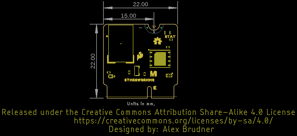
- Board Dimensions
- Datasheet (STM32WB55MMG)
- Datasheet (STM32WB55xx)
- Reference Manual (STM32WB55xx)
- GitHub Hardware Repo


 CNC Routers")
