

The 555 Timer is a widely used integrated circuit designed to generate various output waveforms.
Multivibrators and CMOS Oscilators can be make with some electronic components for generating square wave outputs. But 555 IC designed for same outputs waveforms using some extra timing components.
555 Timer designed by Han R. Camenzind in Switzerland at 1970. Camenzind announced the 555 timer as “Integrated time machine”. It produced by Signetic Company. 555 IC is sold worldwide in millions of years because easy to use, affordible. A standart 555 IC consists: 25 Transistors, 2 Diodes, 15 resistors, plastic case and 8 legs.

555 Timer Integrated Features
► One of the most important features of the flip flop, such as the counter is used in most circuits in the square wave signal. With the 555 integration, we can achieve this square wave easily. Other features;
► There is a sharpening of impact width,
► Impact width is not affected by supply voltage.
► Has supply voltage between 4.5 – 16V,
► A long pulse width can be achieved,
►It can give enough current to light a lamp. Up to 200 mA output current can be obtained,
►Timing settings can be changed with RC circuit to be added to the circuit.
Other Self-Timer Integrated Types


555 Applications
- Time Delay Generation with 555
- Pulse generation
- Pulse Width Modulation(PWM) with 555
- Precision Timing
- Sequential Timing circuits
555 Pinouts


| 1 | GND | Ground, low level (0 V) |
| 2 | TRIG | OUT rises, and interval starts, when this input falls below 1/2 of CTRL voltage. |
| 3 | OUT | This output is driven to approximately 1.7V below +VCC or GND. |
| 4 | RESET | A timing interval may be reset by driving this input to GND, but the timing does not begin again until RESET rises above approximately 0.7 volts. Overrides TRIG which overrides THR. |
| 5 | CTRL | “Control” access to the internal voltage divider (by default, 2/3 VCC). |
| 6 | THR | The interval ends when the voltage at THR is greater than at CTRL. |
| 7 | DIS | Open collector output; may discharge a capacitor between intervals. In phase with output. |
| 8 | VCC | Positive supply voltage is usually between 3 and 15 V. |
Sample 555 projects
Project 1- 555 timer transistor driver circuit
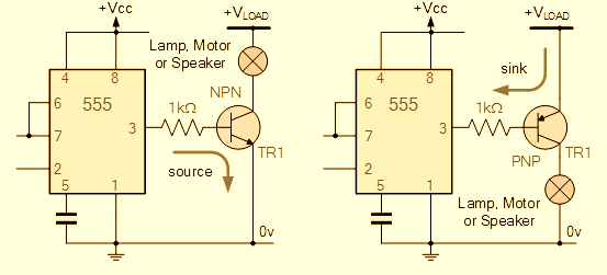
The 555 circuits above can be use to drive loads via transistor. The circuits at the right used NPN transistor. Other circuit used PNP transistor for driving loads. (Exp: Lamp, motor etc..)
Project 2- Astable multivibrator circuit with 555 IC

Above picture shows astable multivibrator circuit. Astable mode is free working mode. It can be used as a 555 oscillator. It is used in LED and lamp flashlights, signal generation, logic clocks, tone generators, security alarms and etc.
Project 3- Electronic Metronome

This is simple metronome circuit using 555 oscillator. This circuit is generate audible sound. Output pulses controlled by 150k potentiometer.
Project 4- Police Siren Circuit with 555

Do you like police siren? If yes, You can simulate police siren sound with this 555 circuit. Output sound frequency are 300 Hz and 660 Hz in 0.5 seconds.
555 DataSheets
There are several 555 IC manifacturer. At the same time there are several 555 IC models: LMC555, NE555


 CNC Routers")
")