What is a spectrum Analyzer?
A spectrum analyzer is an electronic instrument used to measure and visualize the distribution of power in the frequency domain, typically for electrical signals. It operates by breaking down a complex signal into its individual spectral components, allowing engineers and technicians to see the spectral content of the signal, such as its frequency, amplitude, and phase. This information is useful for a variety of applications, such as wireless communications, audio engineering, and EMI testing.
What is PT2314?

PT2314 is a monolithic integrated circuit produced by Princeton Technology Corp. It is a stereo audio processor that provides tone control, volume control, balance control, and other functions for audio systems. The PT2314 is commonly used in compact audio systems such as boomboxes, bookshelf speakers, and car audio systems to provide a user-adjustable audio experience. The chip includes an internal volume control, tone control, and mixing functions, which reduces the number of external components needed and simplifies the design process.
PT2314 Pinouts

The PT2314 is a 28-pin DIP (dual in-line package) integrated circuit with a variety of input/output pins and control pins. The exact pinout of the PT2314 may vary slightly based on the specific datasheet or version, but a typical pinout is as follows:
- Ground (GND)
- Left audio input (LIN)
- Right audio input (RIN)
- Volume control (VOL)
- Bass control (BASS)
- Treble control (TREB)
- Balance control (BAL)
- Loudness control (LOUD)
- Mute control (MUTE)
- Stereo/Mono control (ST/MO)
- Standby control (STDBY)
- Left audio output (LOUT)
- Right audio output (ROUT)
- +VCC (power supply)
Other pins may include reference voltage outputs, internal signal test points, and other control inputs. The pinout and functions can be confirmed by consulting the datasheet or the manufacturer’s specifications for the specific PT2314 device being used.
PT2314 Sample Applications
The PT2314 is a versatile integrated circuit that is commonly used in a variety of audio applications. Some common applications of the PT2314 include:
- Portable audio systems: The PT2314 is often used in boomboxes, portable speakers, and other portable audio devices to provide tone control, volume control, and other features.
- Car audio systems: The PT2314 is often used in car audio systems to provide tone control, volume control, and other features.
- Home theater systems: The PT2314 is sometimes used in home theater systems to provide tone control, volume control, and other features.
- Professional audio systems: The PT2314 is sometimes used in professional audio systems, such as mixing desks and PA systems, to provide tone control, volume control, and other features.
- DIY audio projects: The PT2314 is often used in DIY audio projects due to its compact size, low cost, and versatile feature set.
Note that the specific use case of the PT2314 may vary depending on the specific design requirements and the intended application. It is important to consult the datasheet and manufacturer’s specifications for the specific PT2314 device being used to ensure proper implementation.
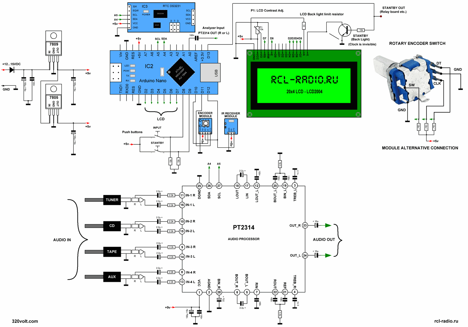
Spectrum analyzer with arduino using PT2314

All schemes and codes:
I can provide you with a general explanation on how to build a PT2314-based spectrum analyzer circuit with an Arduino.
Here are the basic steps to build a PT2314-based spectrum analyzer with an Arduino:
- Connect the audio input to the PT2314: Connect the left and right audio inputs (LIN and RIN) of the PT2314 to the audio source.
- Connect the PT2314 to the Arduino: Connect the left and right audio outputs (LOUT and ROUT) of the PT2314 to the analog inputs of the Arduino.
- Power the PT2314: Connect the +VCC and GND pins of the PT2314 to a suitable power supply.
- Write the Arduino code: Write an Arduino sketch that reads the audio data from the analog inputs, processes the data, and displays the spectral content on an OLED display or a PC interface.
- Test the circuit: Test the circuit and ensure that the spectral content of the audio signal is displayed correctly.
Note: The above steps are just a general guide and the specific details of the circuit will depend on the exact configuration and design requirements. It is important to consult the datasheet and manufacturer’s specifications for the specific PT2314 device being used to ensure proper implementation.


